

AHA board: an easy-to-use configurable IoT platform for hands-on experiments on sensing and intelligent decision-making using AI.
Description:
The AHA (AI Hardware Adventure) platform, developed by Dr. Swarup Bhunia and the students in the Nanoscape Lab, provides a hands-on, game-based learning introduction to intelligent edge computing and the key principles of system operation for undergraduate students from any disciplines. Students perform a set-of well-designed experiments with the AHA hardware platforms to understand the underlying hardware components (e.g., processor, sensors, data storage) and AI/ML algorithms used for intelligent decision making. In particular, AHA platform enables undergraduate students to perform experiment with hardware sensors (e.g., temperature, motion, light) in IoT applications for monitoring and controlling devices in real-time, and make predictions using data from sensor hardware modules using simple AI/ML algorithms. The students also pursue a design project where the use the AHA platform for build a smart edge computing device for an application of their choice. This project challenges them to explore important community problems that can be solved using the power of intelligent edge devices.

Block diagram for the AHA board showing all major components and interconnection among them.
Download Links:
Testing Manual Examples Ardunio Software VPC Driver Features
1. AHA Board
This section references the hardware design specification of the AHA (AI & Hardware Adventure) board.
1.1 Board, Modules, and Layout
The AHA board consists of the following modules. 1. The AHA baseboard, 2. USB B to Micro-USB Cable (used for charging and programming), 3. Jumper cables, 4. 18650 Li-Ion Battery, 5. Power Management Unit, 6. Oxymeter/Heart Rate Sensor. 7. CPU & Comms Unit, 8. OLED Display, 9. Ultrasonic Sensor, 10. Weather Sensor, 11. Light Sensor, 12. Motion Sensor. All these modules, except for the baseboard, are available from 3rd party vendors.
Though the modules share common pins, attaching the modules in respective positions is strongly recommended. While attaching the modules, verify that the pins on the AHA baseboard match those on the individual modules. Connecting the wrong pins can potentially damage the module and short other modules connected to the AHA baseboard.
The AHA board is very expandable, allowing users to implement a wide range of smart sensory circuits and conduct various experiments that help students learn electronic system design in the age of IoT.
The following hardware components are soldered onto the AHA baseboard, as seen in figure 2.
- 18650 battery holder
- Power switch
- GPIO pins and Power supply pins
- RGB LED with current limiting resistors
- Potentiometer
- Tactile button Switches with pull-up resistors
- Female pin headers for all the modules
The Breadboard present in the center is glued to the AHA baseboard. Attempting to remove that is not recommended as it is very difficult, and if not careful while removing it, the GPIO pins on either side can cause injury.
1.2 Block Diagram and Power Supply Design
Figure 3 shows the block diagram of the AHA board. The main processing block on the AHA board is the CPU & Comms Unit. The “CPU and the Comms Unit” module is an ESP32 microcontroller. The microcontroller has built-in WiFi and Bluetooth. It also handles communication with a Personal Computer (PC) to program and output sensor data.
The “Motion Sensor,” “Oxymeter & Heartrate,” “OLED Display,” “Weather Sensor,” and the “Light Sensor” are connected to the microcontroller by the I2C bus. The Potentiometer is connected to the ADC port of the microcontroller. The RGB LED, and the Switches are connected to GPIO pins of the microcontroller. The GPIO pins and the I2C SPI pins near the breadboard are connected to the microcontroller and provide access to pins that are not connected to any of the modules. SPI pins are connected to the hardware- implemented SPI pins on the microcontroller. Pins 21 and 22 on the microcontroller are connected to the SDA and SCL pins, respectively. The SDA is the data line, and SCL is the clock line for the I2C protocol. Pins 12, 13, 14 & 15 are connected to MISO, MOSI, CLK & CSO pins, respectively. These pins are utilized for communicating via the SPI protocol.
The microcontroller has a Micro-USB port that can be used to upload firmware from a connected PC. The Micro-USB port also provides power to the microcontroller. When powered through the USB port, the Power switch is recommended to be turned off. Sliding the switch off disconnects the battery while the board is powered through the USB port.
The onboard battery allows the AHA board to be tether-free and makes it completely portable. The 18650 Li-Ion battery has a capacity of 2600mAH and can be charged through the Micro-USB port on the battery. The USB cable provided along with the AHA board can program the microcontroller, power the board through the microcontroller and charge the Li-Ion battery.
Note that the battery will not charge unless the Micro-USB cable is plugged into the port on the battery. The battery will not charge through the microcontroller. The battery has small LED lights on the positive terminal (the left terminal); the light turns red when charging and green when completely charged. Please do not keep the battery plugged into the USB outlet for long periods after it is completely charged. The Li-Ion battery has built-in protections, but it is still dangerous of the battery is mishandled.
The output voltage from the battery has a nominal voltage of 3.6V. The Power Management Unit (PMU) regulates this input voltage to 5V. Even as the output voltage from the battery changes, the output voltage from the PMU remains constant at 5V. The Power switch is connected between the battery and the PMU. Sliding the switch to its OFF position will disconnect the battery and the PMU. The microcontroller provides the 3.3V available on the AHA baseboard. The microcontroller has a built-in voltage regulator that converts 5V to 3.3V. The microcontroller GPIO pins run on 3.3V logic, so it does not read 5V logic accurately and may cause damage. To reduce power draw while testing, you can remove unused modules from the AHA baseboard. Please ensure the pin alignment while placing the modules back on the baseboard.
The AHA board is very expandable. It provides the flexibility to use external sensor components through the breadboard and the GPIO pins. Users do not have to use a single sensor module at an instance. The microcontroller can interface with all the sensor modules at the same time. Adding to this, multiple AHA boards can be connected either through wires or using wireless methods. This ability to reconfigure the board enables the AHA platform to be limitlessly flexible, matching the user’s creativity.
1.3 AHA Modules
The specifications and detailed information for the modules that connect specifically to the AHA baseboard are provided in this section.
- Rechargeable Li-ion 18650 Battery
- Fenix ARB-L18-2600U
- 2600mAh
- Micro-USB Charging port
- Max 1A recommended charging current through the USB port
- Overheat Protection
- Overcharge Protection
- Over-Discharge Protection
- 500 Charge Cycles
- Pressure Relief Vents
- 3.6V Nominal Voltage
- LED Battery Charging Indicator
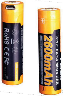
Do not expose the battery to heat or discard it in water. Use of battery under 32°F/ 0°C is not recommended. After extended periods of storage (three months or longer), it may be necessary to recharge the battery to regain maximum performance. Refrain from removing the battery frequently from the battery holder.
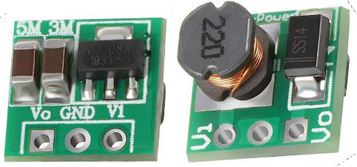
- Power Management Unit
- DC-DC boost converter
- Typical conversion Efficiency of 85%
- 1.5V – 4.2V to 5V
- Do not provide input voltage greater than 5V to this module. It will overheat and damage itself.The output voltage will decrease if the load at output draws more than 480mA or if the input power drops less than the output power.
- Starting voltage 0.8V, output current 7mA
- Input 1-1.5V, output 5V max current 40-100mA
- Input 1.5-2V, output 5V max current 100-150mA
- Input 2-3V, output 5V max current 150-380mA
- Input more than 3V, output 5V max current 380-480mA
- CPU & Comms Unit
- ESP WROOM 32E Development Board
- 2.4 GHz WiFi + Bluetooth® + Bluetooth LE module
- 4MB SPI Flash
- 38 pins (19 pin dual socket)
- Xtensa® dualcore 32bit LX6 microprocessor
- Datasheet
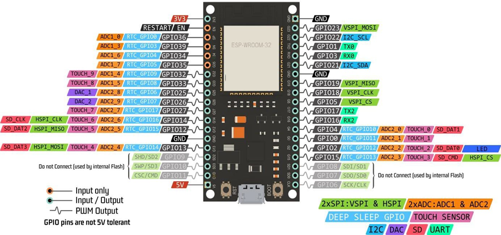
When attaching the microcontroller, match the pin names, WROOM 32, and the Micro-USB marks on the AHA baseboard with the respective labels on the module. If the module is attached in reverse, it will short to ground and can damage other connected modules.
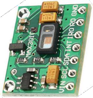
- Oxymeter and Heartrate Sensor
- AX30102
- Sp02 detection
- Heartrate monitoring
- Proximity detection
- LED based Reflective Pulse Oximetry (Photoplethysmography PPG)
- Integrated cover glass over the sensor
- I2C Address 0x57
- Datasheets and user guides
- Module Operating Voltage 3.3V to 5V
- Motion Sensor
- MPU-6050 IMU
- 3-axis gyroscope and 3-axis accelerometer
- Integrated and dedicated 16-bit ADCs for gyroscope and accelerometer
- Onboard Digital Motion Processor for processing 6-axis Motion-Fusion algorithms
- 400kHz Fast Mode I2C compatible. I2C Address 0x69
- Auxiliary I2C bus to access sensors like magnetometers for onboard processing
- Datasheet
- Module Operating Voltage 3.3V to 5V

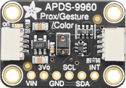
- Light Sensor
- APDS9960
- RGBC Light Sensing with UV-IF Filter
- Proximity sensing
- Ambient Light sensing
- Gesture detectionI2C Address 0x39
- Integrated Optical Lens for Collimating IR LED Beams
- Calibrated to 100mm distance detection
- Datasheet
- Weather Sensor
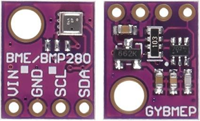
- BME 280
- Barometric Pressure sensing – 300 to 1100 hPa range, with ±1 hPa accuracy
- Humidity sensing ±3% relative accuracy
- Temperature measurement – -40 to 85°C range, with ±1°C accuracy
- I2C Address 0x76
- Datasheet
- Module Operating Voltage 3.3V to 5V
- Range Measurement Module
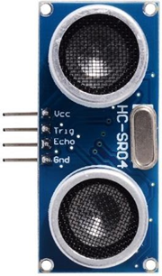
- HC -SR04
- Ultrasonic distance measurement
- 2cm to 400cm range with 0.8cm accuracy
- Effectual Angle <15°
- Measuring Angle 30°
- Trigger input pulse width 10µS (TTL pulse)
- Echo pulse width proportional to the distance
- 40kHz ultrasonic frequency
- Datasheet
- Module Operating Voltage 5V
- Display
- 1.3″ Blue Monochromatic OLED display
- 128×64 dot matrix display
- SSH1106 display driver
- I2C Address 0x3C
- Module Operating Voltage 3.3V to 5V

2. Operating Instructions
2.1 Powering the AHA Board
- Multiple sources can power the AHA board. As mentioned in previous sections, it can be powered by the onboard battery and through the USB port on the CPU & Comms Unit.
- A USB to Micro-USB cable is required to program and power the board through the CPU & Comms Unit. The same cable can be used to charge the battery.
- Sliding the Power Switch adjacent to the battery to the ON position will power the board through the battery if no USB cable is attached to the AHA board.
- When powering the board through the USB port on the CPU & Comms Unit, slide the power switch to OFF. This disconnects the battery connection with the Power Management Unit.
- Please do not leave the battery unattended for long periods when charging. Unplug it after the battery is fully charged.
- It is not recommended to use the battery while it is being charged. Ensure the Power Switch is turned off and the board is not powered through the USB port on the microcontroller.
- Do not charge the battery and power the AHA board simultaneously when the battery is connected to the AHA baseboard. Removing the battery from the holder is not recommended.
- The maximum charging current through the USB port on the battery is 1A. Charging the battery via a USB brick or a USB 3.0(900mA) port will fully charge it in approximately 2 hours, 45 minutes. If the battery is powered through a USB 2.0 slot(500mA), it can take up to 5 hours. The LED indicator turns red while charging and will turn blue once the battery is fully charged.
- Place the board on its legs and make sure it is on a flat surface. Do not keep any under the board. The underside of the board has soldered pins, which are conductive. Placing conductive materials under the board can short the connections and damage the board.
2.2 Power on Check
The LEDs on the Motion sensor and the Light Sensor modules will glow when the board is powered up. If any of the LEDs are not turned ON, the modules and the baseboard need to be troubleshooted for possible errors.
3. Programming the AHA Board
The AHA Board employs an ESP32 microcontroller in the CPU & Comms unit. This microcontroller can be programmed using the Arduino Integrated Development Environment (IDE) software. Users can code in the IDE and upload the code to the ESP 32 from the IDE. Instructions on installing the IDE and how to program the microcontroller are discussed in this section.
3.1 Installing the Arduino IDE
Arduino IDE is open-source software that can be downloaded from their website and run on various platforms, including Windows, Linux, and Mac. The IDE supports many microcontrollers and development boards. Since it is open-source, users can develop custom libraries for the sensors and actuators connected to the microcontrollers. 3rd party libraries are very accessible and can be utilized by users to increase the ease of programming. In the proceeding sections, we will look at setting up the microcontroller and libraries specific to the AHA board. Users can utilize these instructions as a reference even when working with other sensors and microcontrollers as long as they are programming on the Arduino IDE.
- Click on the website here to visit the Arduino IDE download page.
- Select the download package based on the operating system and click on the option to download the respective package.
- After downloading the software package, install it by following the onscreen prompts.
- The red dotted circle indicates where the user should click to install the software. Following the steps shown in Fig6 should help the user install the IDE in Windows based machines.
3.2 Installing sensor-specific libraries
Libraries help the user program efficiently. Most background tasks required for interfacing the sensor with the microcontroller and sensor-specific algorithms are described in the library file. This can simplify the programming while interfacing multiple sensors with the microcontroller. In this section, we will look at three different methods for installing 3rd party libraries for the sensors.
We will install the Library for the Light sensor module for demonstration purposes. The Library we will be installing is “Adafruit APDS9960”.
3.2.1 Installing the libraries through Library Manager
- Open the Arduino IDE. Go to Sketch on the menu bar and then click on Include Library. Click on the Manage Libraries button from the expanded submenu.
- The library manager toolbox will appear. Type the library name in the search box on the right. For the demonstration, we searched for Adafruit APDS9960.
- A prompt will be displayed asking the user to download the required dependencies if the Library has any dependencies. If the dependencies are either already installed or not required, the user can skip them. In our case, we need to install the Adafruit BusIO, so we click on the “Install all” button.
- Let the files download, and when the Library finishes installing, the toolbar updates the status beside the Library.
3.2.2 Installing the libraries by importing a .zip file
For this method, it is expected that the user has downloaded the required .zip library files from a trusted source.
- Open the Arduino IDE. Go to Sketch on the menu bar and then click on Include Library. Click on the Manage Libraries button from the expanded submenu.
- After clicking on the Add .ZIP Library, a menu box will appear from which you can navigate and select the zip file downloaded for the sensor. Select the file and click Open.
- The Library is added and can be viewed in the Include Library submenu under the Sketch menu.
3.2.3 Installing the libraries manually
In the manual method, the user is again expected to have downloaded the required .zip library file from a trusted source.
- Extract the library folder from the zip file.
- Now copy the extracted folder inside your sketchbook folder. The sketchbook folder will have the .ino file that is being worked on.
- To find the sketchbook folder’s location, click the File button on the menu bar.
- Now, the sketchbook address is visible under the Sketchbook location field.
Note: Avoid installing libraries directly to the default Arduino Installation folder. When the IDE upgrades automatically, it deletes previous installations and can delete the library packages from the installation folder during the update process.
3.3 Setting up the IDE for ESP 32 Microcontroller
3.3.1 Installing CP210x drivers – Virtual COM Port USB to UART Bridge
The ESP 32 microcontroller communicates using the UART protocol with the PC. Since a PC cannot directly connect via a UART port, the ESP32 module has a UART to USB converter on board. We need to install the driver for this chip on the PC for the ESP32 module to be recognized by the Arduino IDE. Download the driver here (for windows users) and here (for Mac users). Extract the .zip file downloaded from the website.
3.3.2 Installing the ESP 32 board in the IDE Board Manager
Any development board/ microcontroller programmed through the IDE must be added through the “Board Manager.” When programming a specific device, users are required to select the device from the installed boards before flashing the program. The following instructions will help users install the ESP 32 board to the Arduino IDE.
- Open the Arduino IDE. Go to File on the menu bar and then click on Preferences, as shown in the figure below.
- Beside the “Additional Board Manager URLs” field, enter the following web address. https://raw.githubusercontent.com/espressif/arduino-esp32/gh- pages/package_esp32_index.json. After pasting the link in the field, click OK.
- Now, click the Tools button on the menu bar and then go to the board, which will open a submenu with all the installed boards listed. At the top, click on the Board Manager button.
- After clicking on the Board Manager, a toolbox appears, and in the search bar on the top right, type in “esp32”. Select the option “esp32 by Espressif Systems”.
- Let the files download, and when the board finishes installing, the toolbar updates the status beside the board.
- Click the Tools button on the menu bar and then go to Board. In the expanded menu, click on the ESP32 Arduino which further expands to all available ESP 32 board variants. Select the 4th board in the list named “ESP32 Dev Module.”
3.4 Flashing the Microcontroller
The IDE opens to a code editor in which the users can write/modify programs that can then be programmed onto the microcontroller. As discussed in the previous sections, the IDE can program many different microcontrollers, even simultaneously. So, it is important to configure the IDE to reduce the chance of compiling the program for a different microcontroller than for the one required. Step 6 in Chapter 3.3 describes configuring the IDE for the microcontroller specific to the AHA board.
Now assuming that we have a code ready to test, follow the instructions below to program a microcontroller with the Arduino IDE.
- Open the Arduino IDE. Go to File on the menu bar and then click on Open. This opens up a window through which you can navigate the “.ino” file, which has the programming for the microcontroller. Click on the Open button to load the program onto the Arduino editor.
- Now that the editor has loaded the program click the Verify button on the left-hand corner just below the menu bar to compile the code. In this step, errors in programming are displayed in the console window (the black space below the editor) to aid the user in correcting the error. The code is compiled for the specific microcontroller. This is essential, and following Step 6 in Chapter 3.3 ensures you configure the IDE for the exact microcontroller on the AHA board.
- If the IDE detects no error in the code, it displays a “Done Compiling” message with info regarding the program in the console window.
- Since the IDE can flash multiple microcontrollers simultaneously, it is important to set the “Port” configuration so the IDE programs the intended microcontroller. For example, we could upload the same program to two or more AHA boards connected to a single PC at the same time. The computer assigns each connected board a specific “port”. These ports are numbered, so each port is labeled after the port number. Let’s say AHA-1 and AHA-2 are connected to a single PC. The PC assigns “COM 26” to the AHA-1 board and “COM 1” port to the AHA-2 board. We now have to specify which port we want to use to program the IDE’s microcontroller. To do this, go to Tools on the menubar and then click on Port. To follow up with the example, let’s program the AHA-1 board. In the submenu beside the Port button, select “COM 26” to program the AHA-1 board.
- Next, click the Upload button beside the Verify button to flash the microcontroller. A progress bar will now appear on the right side over the console window as the code is compiled again.
- When the IDE starts to upload the program, the console window will update the user with information related to the process. Finally, a “Done uploading” message is displayed upon successfully flashing the microcontroller.
3.5 Viewing the Output- Serial Monitor
The IDE can read the microcontroller output through the serial port using Serial Monitor. As programmed, the microcontroller will output data at a specified baud rate.
- The number represented within the Serial.begin() option in an Arduino code represents the baud rate specified in the program.
- To view the output data through the Serial Monitor, click on the tools button on the menu bar and then click the Serial Monitor button.
- It is important to match the baud rate in the Serial Monitor window to match the baud rate set in the program. Failing to do so might result in the Serial Monitor displaying inaccurate data, which can sometimes be illegible as the alphabet characters get translated into different character symbols.
- To read the data correctly, set the baud rate on the Serial Monitor window to the value in the code. In our case, it is 115200 as seen in the code’s Serial.begin() object. And as soon as the right baud rate is set, we can see the output data being printed in the Serial Monitor window.
4. Self-Test Board Verification and Troubleshooting
A verification program named “Self-Test.ino”is available for download here. This program can test the AHA modules and the base board. The program utilizes all the modules and outputs individual sensor data. At the same time, this program also displays data through the OLED screen and enables users to interact with the board through the buttons and the Potentiometer. This program can be used to identify faulty sensors, invalid connections, Input-Output functions, and other possible errors.
Using the instructions in Chapter 3, you can flash the AHA Board with “Self-Test.ino” program and test if the board functions correctly.
After flashing the AHA board with the self-test program,
- Green LED lights on the Motion Sensor and Light Sensor modules should remain ON.
- The OLED display turns ON and will display the text.
- The RGB LED should turn ON and display the Blue color. Press the push buttons to cycle the color to Red and Green.
- Turning the potentiometer knob should change the text on the OLED screen.
- Open the Serial Monitor Window from the Arduino IDE. The window should display the connected Modules and the data from the Distance Sensor.
If any of the outputs are not visible or if any of the sensor/sensor data is not showing up, the board needs to be inspected by the Course Instructor for possible faults.
5. Creating a Wi-Fi Access point/ Hotspot
In this section we provide instructions on how to set up a WiFi access point through Android based smartphones and Windows 10 & 11 based computers by creating “WiFi hotspot” through the devices. This tethered connection acts as access points for the ESP 32 to the Internet. If the devices themselves do not have access, then the resulting network would be “local” and will provide internet access to the microcontroller.
5.1 Creating an Access point/ hotspot on Android Devices
Please note that the exact step might vary depending on the version or variant of Android OS you are using, but the process approach remains the same.
- Open the Settings app on your Android smartphone. You can usually find it in the app drawer or by swiping down from the top of the screen and tapping the gear icon.
- In the Settings menu, scroll down and look for the “Network & internet” or “Connections” option. Tap on it to proceed.
- Within the network settings, you should see an option called “Hotspot & tethering” or a similar option. Tap on it to access the hotspot settings.
- In the Hotspot & tethering menu, you’ll find different types of tethering options. Look for “Wi- Fi hotspot” or “Portable Wi-Fi hotspot” and tap on it.
- On the Wi-Fi hotspot screen, you’ll see a toggle switch at the top. Make sure it is turned on to enable the hotspot feature.
- Once the hotspot is enabled, you can customize the settings. Tap on “Set up Wi-Fi hotspot” or “Configure Wi-Fi hotspot” to access the configuration options.
- In the configuration screen, you can set the Network name (SSID) for your hotspot. This is the name that will be displayed when other devices search for available Wi-Fi networks. Please note this name, as we must enter this into the code using the IDE when programming the ESP 32.
- Below the Network name, you can set the Security type and password for your hotspot. Choose “WPA2 PSK” as the security type and enter a secure password of your choice. Please remember the password, as we must enter the very same into the code using the IDE when programming the ESP 32.
- Make sure you select the 2.4 GHz band option in the configuration screen. ESP 32 is currently only capable of connecting to 2.4GHz band WiFi.
- After setting up the network name and password, tap on the “Save” or “Done” button to save the settings.
- Once the device is connected, it should have access to the internet through your Android smartphone’s mobile data connection. In some devices, if the LTE/5G data is disconnected, internet access is provided via a WiFi connection.
- To turn off the hotspot, simply go back to the Wi-Fi hotspot screen in the Settings menu and toggle the switch to the off position.
5.2 Creating an Access point/ hotspot on Windows 10 & 11 Devices
- Open the Start menu by clicking on the Windows icon at the bottom left corner of your screen.
- Click on the “Settings” gear icon. It is typically located above the power button. Or type “Settings” in the search bar found at the top of the Start menu.
- In the Settings menu, click on the “Network & Internet” option on the panel towards the left- hand side.
- In the Network & Internet settings, select the “Mobile hotspot” tab.
- On the Mobile hotspot screen, you’ll find a toggle switch at the top. Click on it to enable the hotspot feature.
- Before enabling the hotspot, make sure to configure hotspot settings correctly.
- Click on “Edit” button to configure the Network properties (SSID/Name, Password, Band). Please remember the SSID/Name and the password, as we must enter the very same into the code using the IDE when programming the ESP 32.
- Make sure you select the 2.4 GHz band option in the configuration screen. ESP 32 is currently only capable of connecting to 2.4GHz band WiFi.
- After setting up the network Name, Password and the Band, click on the “Save” button to apply the changes.
- Once the device is connected, it should have access to the internet through your Windows device’s internet connection.
- To turn off the hotspot, go back to the Mobile hotspot screen in the Settings menu and toggle the switch to the off position.
Developers
- Dr. Swarup Bhunia
- Rohan Reddy Kalavakonda
References and Acknowledgement
You can visit the following websites for more details regarding the sensor modules and their specifications. Also provided are the links for websites where you can find additional content on how to work with the Arduino IDE, ESP 32 microcontroller and the sensor modules.
- https://www.espressif.com/sites/default/files/documentation/esp32-wroom-32e_esp32- wroom-32ue_datasheet_en.pdf
- https://invensense.tdk.com/products/motion-tracking/6-axis/mpu-6050/
- https://www.analog.com/en/products/max30102.html#product-overview
- https://cdn.sparkfun.com/assets/learn_tutorials/3/2/1/Avago-APDS-9960-datasheet.pdf
- https://www.bosch-sensortec.com/media/boschsensortec/downloads/datasheets/bst-bme280- ds002.pdf
- https://www.makerfabs.com/desfile/files/HC_SR04%20Datasheet.pdf
- https://docs.arduino.cc/built-in-examples/
- https://docs.arduino.cc/hacking/
- https://support.arduino.cc/hc/en-us/articles/9207690465436
- https://docs.arduino.cc/software/ide-v1/tutorials/installing-libraries
- https://www.espressif.com/en/products/socs/esp32
- http://esp32.net/usb-uart/
- https://www.silabs.com/interface/usb-bridges/classic/device.cp2102?tab=specs
- https://www.silabs.com/developers/usb-to-uart-bridge-vcp-drivers
The following links provide additional content to explore the ESP32 microcontroller with the Arduino platform.
- https://randomnerdtutorials.com/getting-started-with-esp32/
- https://randomnerdtutorials.com/installing-the-esp32-board-in-arduino-ide-windows- instructions/
- https://randomnerdtutorials.com/projects-esp32/
Development and continuous enhancement of the AHA Platform is supported in part by National Science Foundation (NSF) grant #2405373, “Collaborative Research: Engaging High Schoolers in Integrated Computer Science and Engineering Through Hands-On Experiences with Microelectronics and Artificial Intelligence”. Lead PI of the grant Prof. Pavlo Antonenko and Co-PI Prof. Andrea Ramirez-Salgado have made extensive contributions on developing the training materials (hands-on experiments, design projects, games) on AHA platform and on-going evaluation of the AHA platform for diverse student population.